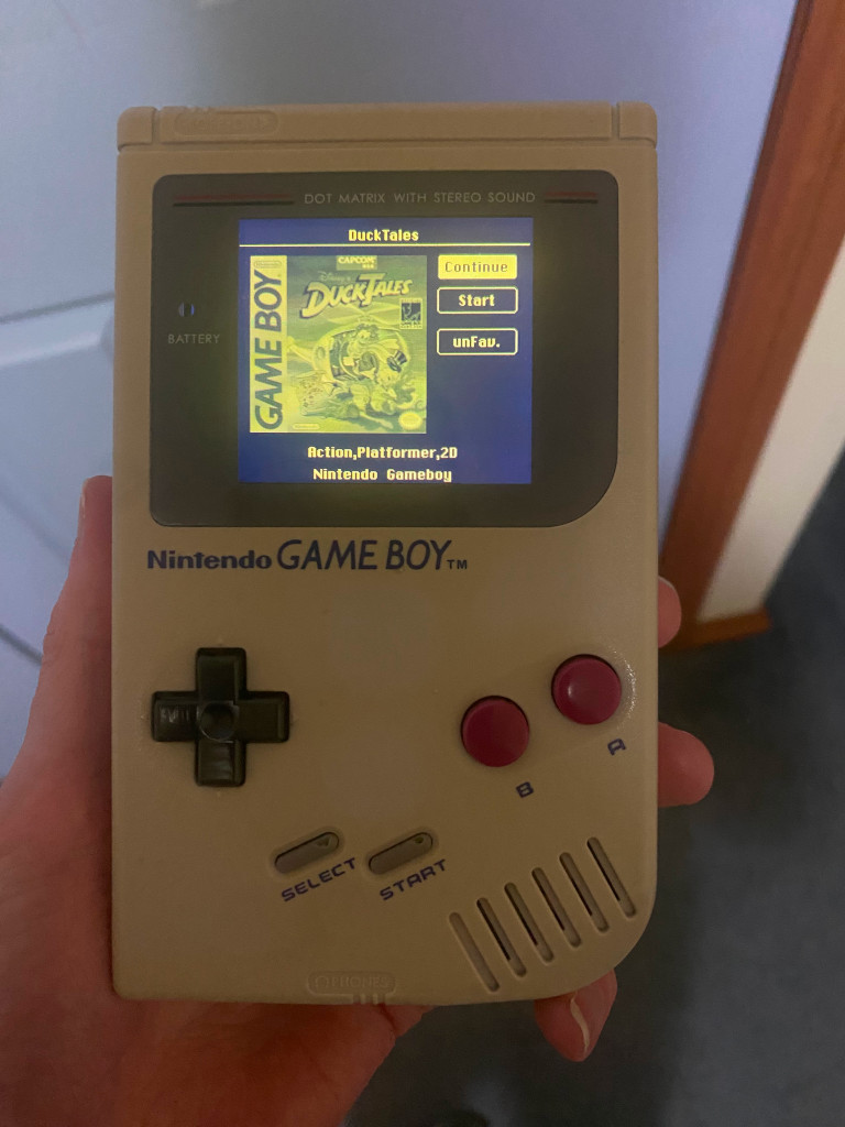
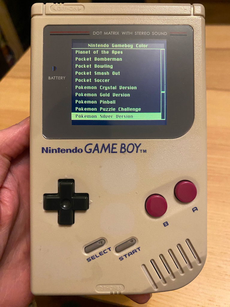
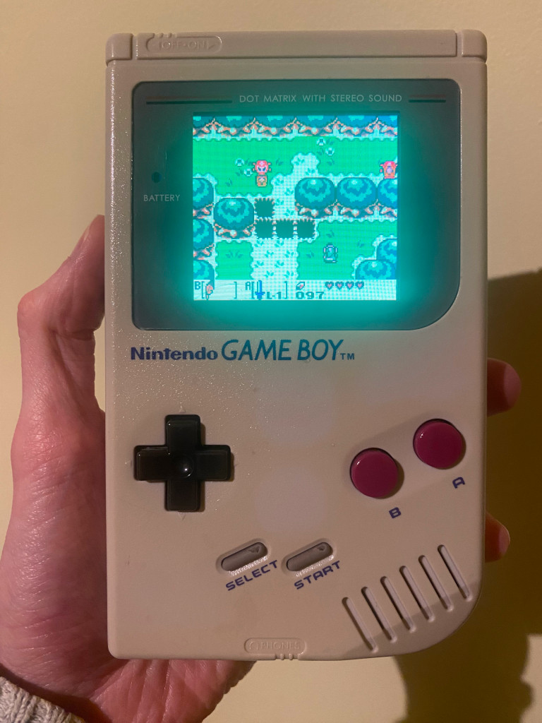
Gameboy DMG ESP32
Disclaimer
I'm not an expert and proceed with all due caution. No warranty, liability or anything else are implied or
provided.
Follow instructions at your own risk.
Credits
This project is based off of the ODROID
Go which has been discontinued but I would not have figured this out
without
this project.
Software is based off Retro Go which I changed
probably 0.00000001%
Front PCB designed by Bucket mouse
Equipment
- Scalpel knife to remove some small bits of the case
- Dremel to remove some larger bits
- 3D printer for cartidge (I use Mono Photon)
- Hot glue gun (of course :) )
- Soldering iron
Parts
ESP32 Wiring
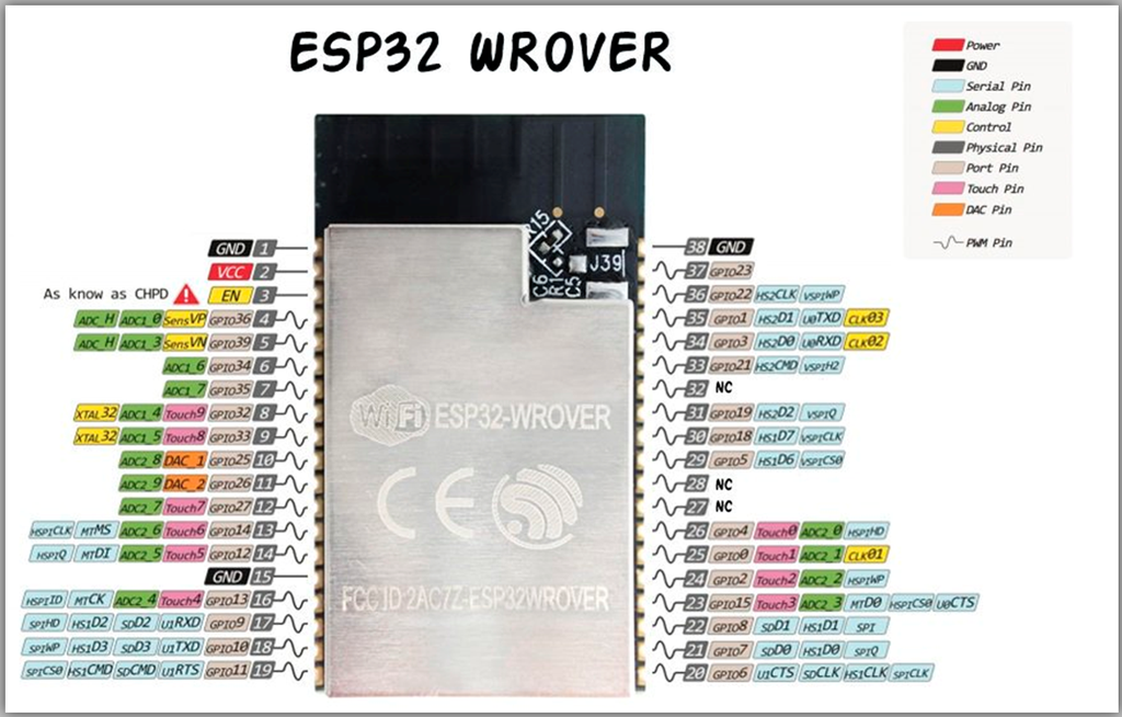
buttons - connect to gnd
- Up - 35 *
- Down - 36 *
- Left - 34 *
- Right - 2
- A - 13
- B - 33
- Start - 39
- Select - 27 *
- Menu - 0 **
sd card
- MISO - 19 *
- MOSI - 23
- CLK - 18
- CS - 22
lcd card
- MOSI - 23
- CLK - 18
- CS - 5
- DC - 21
- RST - 14
external I2C DAC
- BCK - 4
- WS - 12
- DATA - 15
serial port
- Txn - see serial port section
- Rxn - see serial port section
* Needs to be held high ( connect 3.3v -> 10k resistor -> Pin )
** This is the boot pin so normally already held high
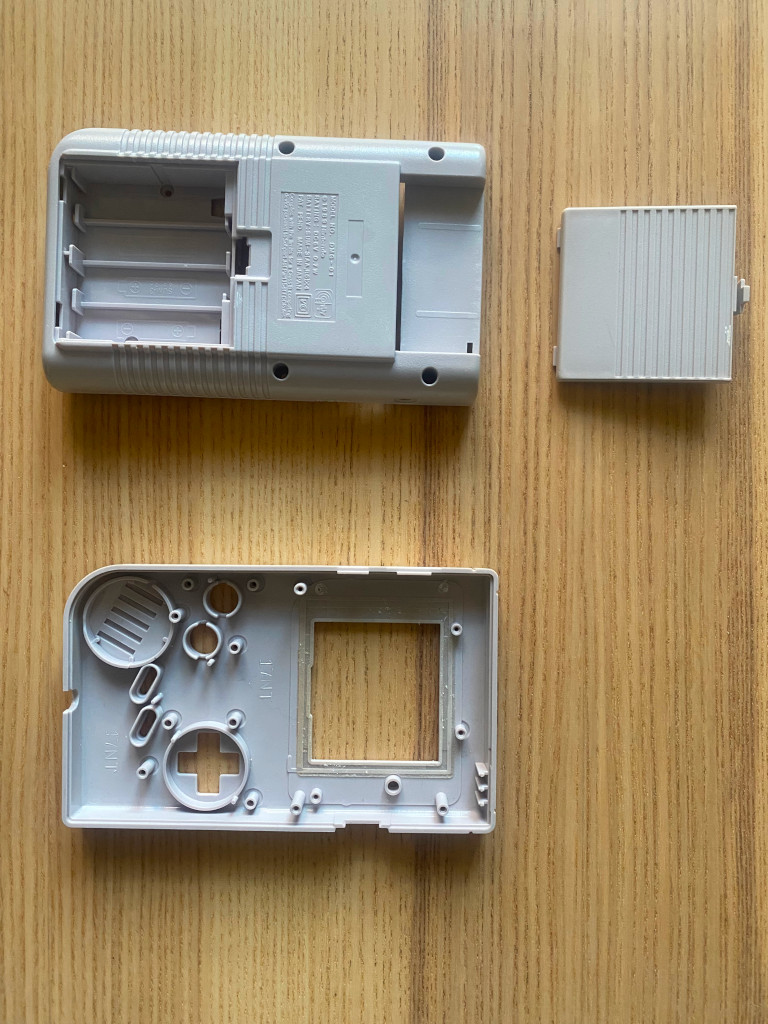
Case
The case is a standard gameboy DMG case you can use a reshell too since non of the original DMG circuitboards
are
needed.
Remove all parts including the metal panel near the cartidge slot.
For this project I removed the guts and transferred to a repo shell.
At this point you can use some peroxide (or retrobrite as it's referred to) to brighten the shell and do some
cleaning.
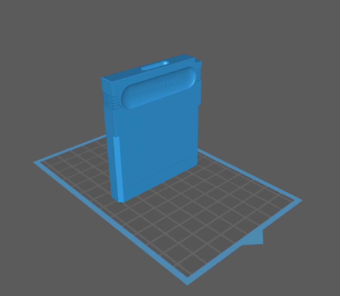
Cartridge
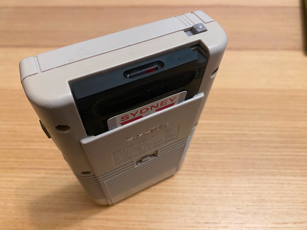
The cartidge I designed in blender by eye balling a cartridge and using a ruler; here's stl file.
Printed using my 3d printer. The outside was a little rough so I sanded it down with fine sandpaper.
I trimmed some of the front that
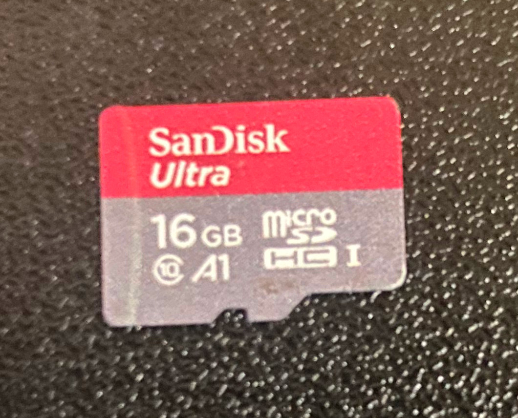
SD Card
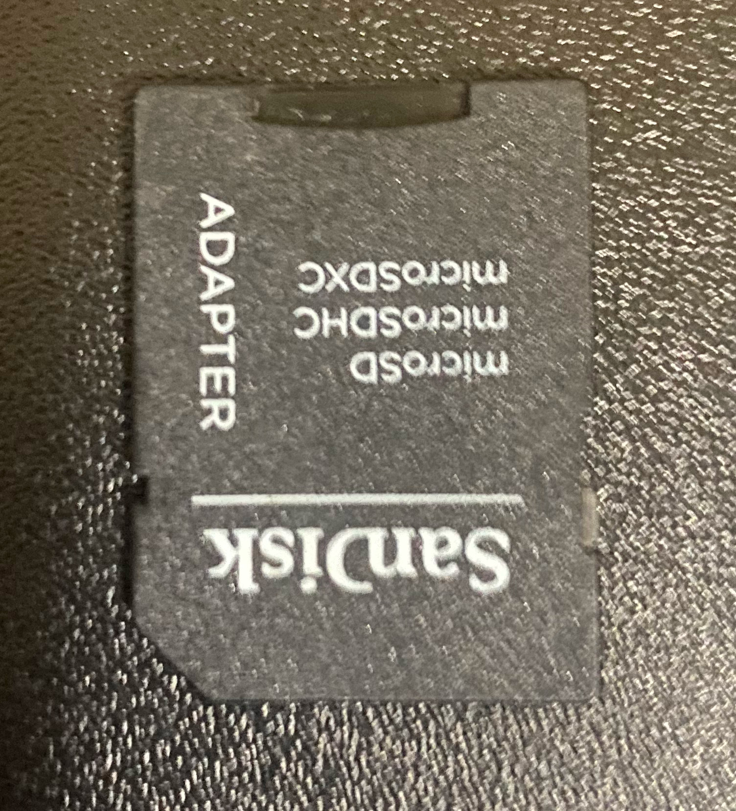
For the SD card I used this micro sd card, 16 GB is plenty (everything atm is less than 3GB).
I used the SD card adapter than comes with this micro sd card to hold the card and allow it to be swapped out if
the card becomes damaged or corrupt.
Cut the adapter about halfway and line up with the opening in the cartidge printed earlier
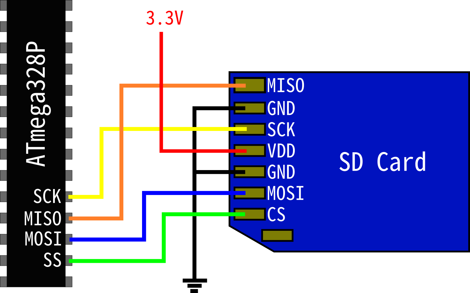
The wiring of the adapter is here:
Folder structure
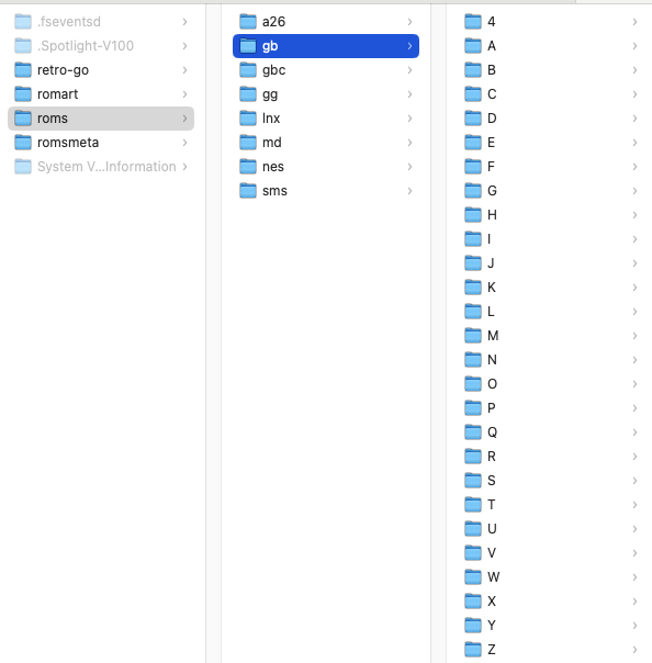
The folder strucutre of the sd card is the same asretro-go's on. I deviate from retro go when it comes to the
images and meta data.
Instead of using the romart folder I created a new one called romsmeta.
This folder's stucture should match the folder structure of the roms folder.
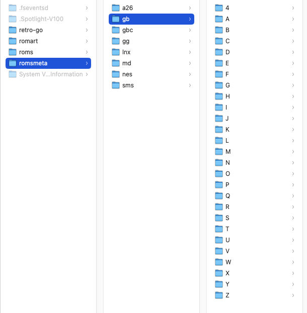
The folder should also contain; per rom, the following files:
- ROMNAME_INCLUDING_EXT-grayscale.png (cover image in grayscale)
- ROMNAME_INCLUDING_EXT.png (cover image in colour)
- ROMNAME_INCLUDING_EXT.txt (game meta data)
An example of this for F1 on the gameboy:

The format of the txt file is this (some lines are ignored as they were for stuff that didn't make the cut like game
description etc):
IGNORE
Game title
Release date
IGNORE
IGNORE
Genres
Developer name
IGNORE
LCD
Probably the biggest pain with this display is the ribbon cable with 50 pins and no breakout board.
The spec for the display is available here.
It's a little hard to understand but this is how I wired it:
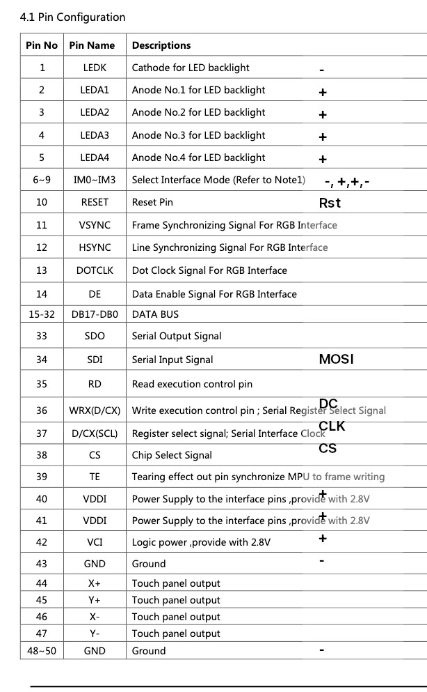
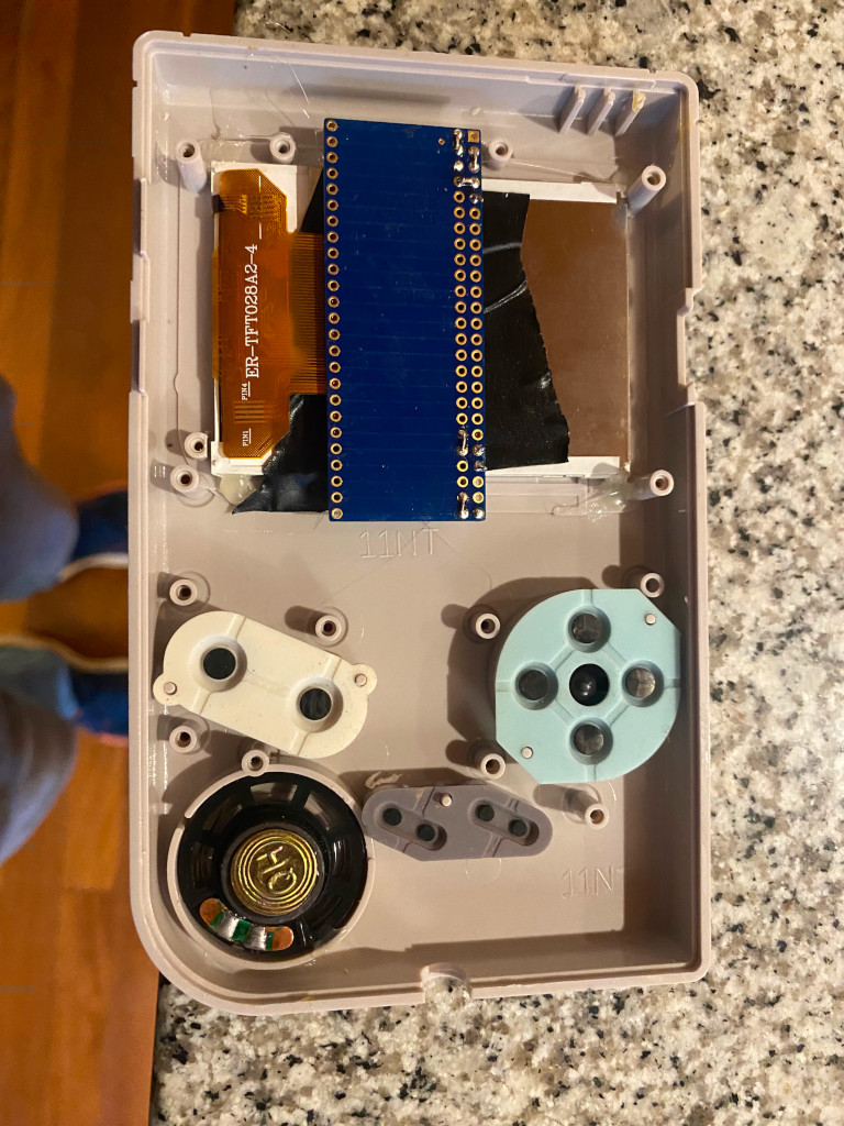
I soldered the 50 pin connector to the breakout board with a lot of flux and tested the connections with a
multimeter one..... by.... one :( , then hotglued the lcd in place
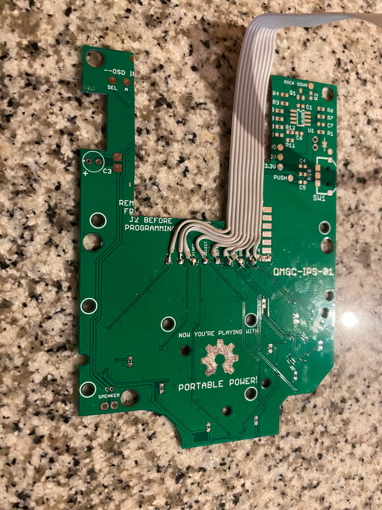
'Front' Controls PCB
The PCB used for the controls I got from PCBWay, the pcb is meant to be used to house a GBC in a DMG shell.
I really only needed the button bit so I cut some bits out until I could stick the LCD breaout boarde and glued
it in place.
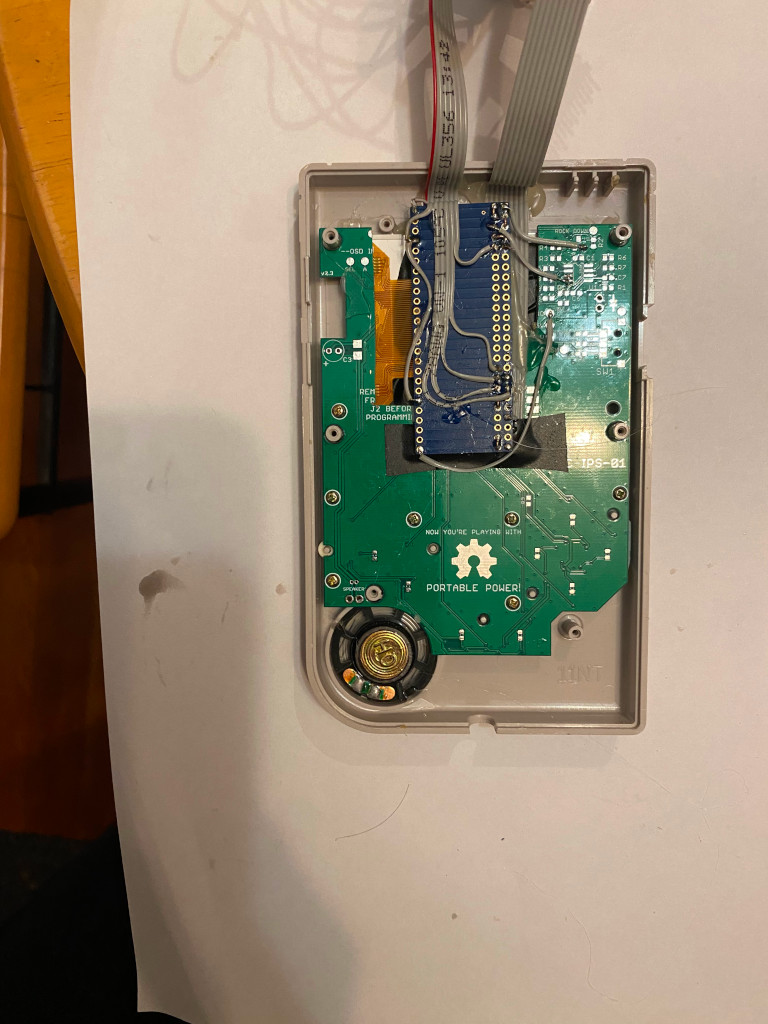
'Back' PCB
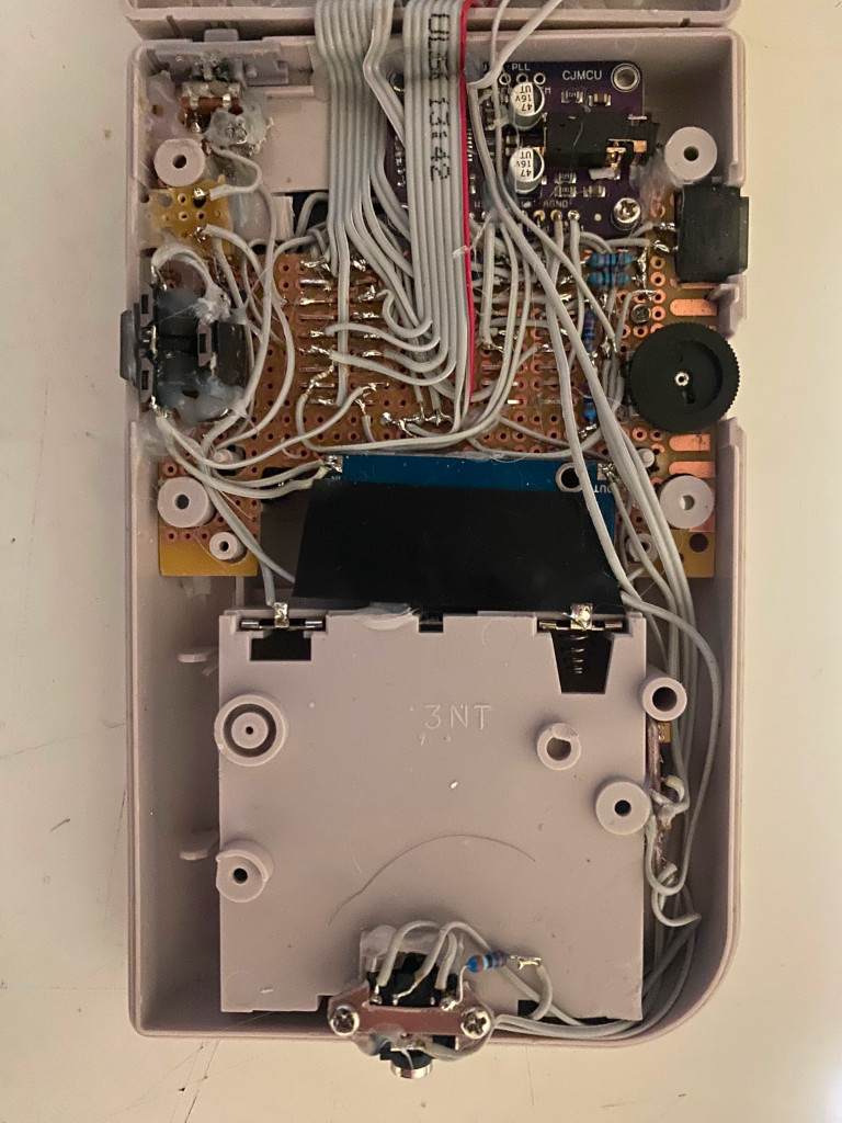
I used a perforatted board for everything to sit on, the esp32 I placed underneath to save vertical room.
To make it fit I cut away with a Dremel and then cut a space at the bottom to fit the power stabiliser.
Once the pcb fit I drilled 4 holes and screwed it to the shell so it stayed secure.
Audio
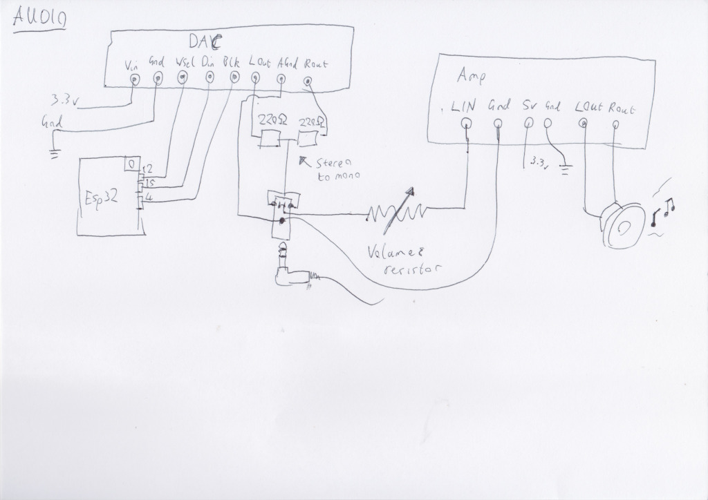
The audio from a ESP32 isn't the best so I've used a DAC convertor to output the sound, since space is tight
I've put it up in the top right
The convertor outputs stereo so I use two resistors to combine the audio to mono.
To control the output volume I use the standard volume control from the GB DMG. They go from 0 -> 10K so they
are enough to be
completely silence the speaker at full resistance.
I couldn't find a nice easy way to have the headphones and speaker both work off this resistor so I hooked it
only
up to
the speaker and left the headphones at a constant volume.
The audio is amplified through a low voltage amplifier (I'm not sure if something a bit
lower
in
voltage draw would be better..._
Power

The build uses 4 AA batteries to power things like the original DMG. If you are using a new shell you'll need to
get some battery connectors since the main Gnd and Power pins are attached to the DMG circuit board (see parts
section).
To secure these connectors I hotglued them in place.
Staying faithful to the original I added a power barrel connector. The cable is an old USB cable with one end
removed and a GBC male connector added.
Note that the Power is on the outside and the Gnd on the inside of the connector. Use a multimeter to confirm or
you may fry things :)
In the gameboy I used a GBC port with some hotglue was used to keep it in place
Next is the power switch, I used a small switch and
then used some hotglue to make the tiny switch fit a bit more snug in the dmg original slide switch.
It feels a little flimsy until you close the case so it seems ok but maybe needs a slightly better switch....
Connect up the switch as so:
To stablise and reduce the power to the ESP32 3.3v power (batteries are 6v and the usb is 5v) I used the power
stabliser mentioned in the parts section.
You'll need a multimeter to check the output voltage and turn the tiny brass screw anticlockwise until you see
the voltage dropping to 3.3v
Serial port
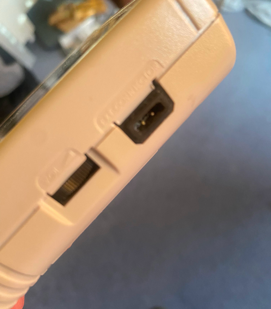
To allow read / writing to the ESP32 I added a small port where the Gameboy link would be normally.
The port I designed in blender and printed using my 3d printer, here's stl file..
To add to the Base PCB; I removed a couple of angular pins from this: drilled a couple of holes through the port
and pushed them through.
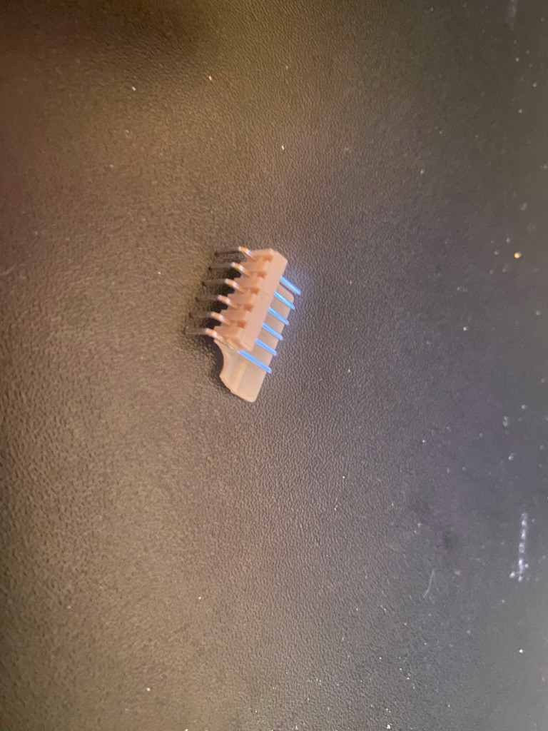
Attach Txn and Rxn pins to these 2 pins.
Now you can write and read from the gameboy. I usually use a ESP32 dev board for this, like this:
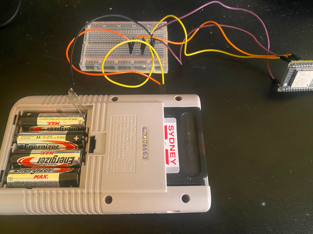
Put ESP32 dev board EN to Gnd
Connect ESP32 dev board Txn/Rxn to corresponding gameboy ports
Connect ESP32 dev board Gnd to Gameboy Gnd (I use a paperclip in the battery compartment, alternatively you
could add ground to the serial port as there's room there)
There's no Rst pin so what I do is hold the Menu button when switching on the gameboy to put into write mode and
then once written toggle the power.
Software
For compiling I used ESP IDF version v4.3
Code for the gameboy can be found here.
I made a good few changes to the software originally from Retro Go, it's a fork so you can compare the changes
and add/remove your own.
In my version I used the Chicago font but since I don't have a license to distribute that I've removed it from
the code.
Improvements
Think biggest improvement would be to reduce the amount of breakout board by designing a custom PCB for the top
part
of
the dmg and one for the bottom.
Battery wise using AA batteries could be improved with using Lipo battery. There's plenty of room in the battery
compartment for an adequete lipo battery, the barrel connector could could charge a lipo charger connected to
the
lipo
battery.
The LED on the gameboy could be the battery charged status led if you use a multi coloured led which would be
rad.


